How to Optimize Electrical Distribution Design in Large Data Centers
Following my first blog post about Schneider Electric’s data center reference design 107 (RD107) for colocation applications, we explained the specific design choices related to the low voltage (LV) part of the design. This second blog post will be more generic (and a bit more technical) on ways to optimize your electrical distribution network.
Electrical distribution design and sizing is mainly driven by three parameters: voltage, current and short-circuit current. The type of equipment, the size of the conductors, and – at the end of the day – the cost are all impacted by those three parameters.

Optimizing electrical distribution means building the electrical architecture by specifying certain key components to use the most efficient equipment at the right place. It is always more cost efficient to use the most common equipment with standard performance levels enabling you to avoid using high-end products with lower production volumes that tend to be used only for specific niche applications and environments.
MV Distribution Optimization Points for Large Data Center Applications
Optimizing the design should start with the medium voltage (MV) portion which is probably the most variable part of the large data center design. For MV distribution there are two main factors to consider:
- Connection to utility MV distribution network
- Medium/large sites (<~20MW IT) connected at the MV level directly to the grid. The voltage level and the short-circuit current level are imposed by the distribution grid. In most cases, the utility company has already implemented a design with a low level of short-circuit current (<16kA) in order to optimize the cost of their own equipment.
- Large and extra-large sites connected to high voltage (HV) transmission grid through a large power transformer: In this case it is possible to choose the MV voltage level and the short circuit impedance of the transformer. This enables you to adapt:
- Current rating: try to avoid exceeding 2500A for primary distribution and <1250A or <630A for secondary level
- Short-circuit rating which depends mainly on the transformer characteristics. It is possible to adjust the power transformer short-circuit impedance which normally is around 11% for 20 to 40MVA range transformers and easily designed to 15-17% without added cost and equivalent power losses. (Read more in our White Paper 258 on specifying transformers at large sites).
- Backup generator set configuration
- De-centralized generators set are usually placed at the LV level. In that case the MV distribution is not critical for the site availability, there are simple protection schemes and few or no controls needed. In the case of where there is a site connected to HV transmission grid, it would be best to use the same MV voltage level as the local distribution grid and to keep the short-circuit current <20kA and as much as possible keep the switchgear at <630A. Doing so will make it possible to use simple switchgear like with “Ring Main Unit” function.
- Centralized MV backup generator power plant. When it is possible to choose the MV voltage level, it is best to use the native generator voltage which is commonly 11kV (50Hz) or 13,8kV (60Hz). In this centralized MV generator case the MV distribution will become critical for the site availability. Most of the time this means there will be more complex protection and control systems requiring more advanced functionality which are not available with basic switchgear ranges. Then the optimized short-circuit current rating will be more <25kA also to limit the cable size. For the generators the most important thing to do will be to choose the maximum number of gensets running in parallel and to check the short-circuit peak current. Most of the time, these are the main constraints for generator applications. (Note: When close transition between utility and backup generator plant is required the combination of both sources should be consider for the short-circuit calculation. In most cases that will leads to high short circuit current ratings).
Of course, adaptations for specific site constraints and equipment with higher performance might be needed, but in the table below, I summarize the recommended MV ratings for having a cost-effective MV design (green cells are the parameters that you can adjust):
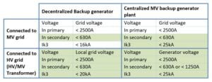 (In primary – current rating of the main MV distribution; in secondary – current rating of the secondary distribution; in Ik3 – short-circuit rating).
LV Distribution Design Sweet Spots for Large Data Center Applications
For the low voltage distribution portion of the design, the MV/LV transformer power rating and short-circuit impedance will be the most important factors for meeting the required performance level of all the downstream LV distribution. (Note: When there are LV generators it is important to do the short-circuit calculation, but most of the time the biggest constraint comes from the transformer. When close transition between utility and generator is required, the combination of both sources should be consider for the short-circuit calculation).
Using a large transformer between 2500 to 4000kVA allows you to reduce the number of LV power trains, as well as reduce the cost of the MV distribution. But, you will be required to use double-pole circuit breakers (ACBs) and double busbars in the main LV switchboard. This, however, leads to high short-circuit current in the LV IT distribution which can driving up cost in the IT room distribution.
Using a transformer below 2500kVA will allow you to use simple pole circuit breakers (ACBs) on the main switchboard while reducing the short-circuit current in the IT distribution.
For the IT distribution the short-circuit current is always a challenge. The simplest way to optimize it and use a MCB at the rack level is to size the rack feeder breaker using selectivity enhanced by cascading between the rack feeder breakers (MCB) and the upstream breakers (MCB). Selectivity enhanced by cascading means the upstream breaker helps the smaller breaker to break the fault current reinforcing its breaking capacity, while selectivity is continuously ensured between both breakers which is key to maximize service continuity.
To size the breaker properly, you need to calculate the potential short-circuit below the rack feeder MCB and to use the “selectivity enhanced by cascading tables” given by circuit breaker manufacturers.
Apply These Recommendations to Your Large Data Center
There is never a single answer and any design needs to be adapted to each case’s unique requirements. However, the design rules I shared with you here in this post are usually the key drivers for optimizing the electrical architecture as you can see in the reference design RD107.
The post How to Optimize Electrical Distribution Design in Large Data Centers appeared first on Schneider Electric Blog.